Overview
The next are the notes extracted from CanAirIO channel in Telegram wrote by @Marvin-YYC user.
Components

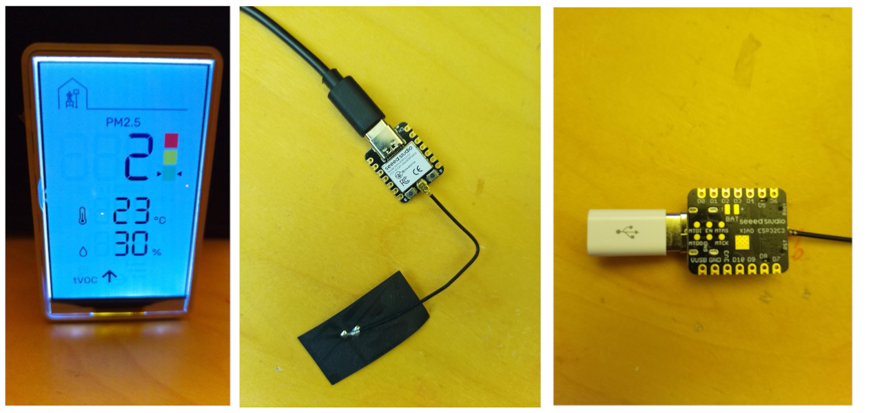
- IKEA Air Quality Sensor type: E2112 VINDSTYRKA
- Seeed Studio ESP32C3 XIAO microcontroller.
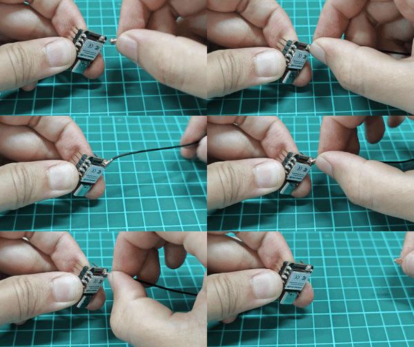
(It is a good practice to connect the radio antenna to the ESP32 before you connect to USB power. Some radio chips can be damaged if you neglect to connect an antenna.)

Firmware
Install CanAirIO firmware on the ESP32. For that:
-
Go to CanAirIO installer and use the web installer to flash the firmware to your the ESP32. Select flavor ESP32C3 SEEDX listed under ‘Special Versions’. Be sure to use a desktop version of Google Chrome or Edge.
-
Once the install has finished select on the ‘Device Dashboard’ select Logs & Console. Hit enter twice and your should see CanAirIO: $ this is the CLI interface.
-
Connect the device to your WiFi by entering the following line on the CLI interface:
nmcli connect YourSSID password "your_password"
Syntax: YourSSID not in quotes your password in quotes. The CLI should indicate that you have connected to WiFi if your credentials were entered correctly.
- Next you need to set your geohash location. Go to this website and select and copy the geohash code for your location. Once you have this code, type:
sgeoh xxxxxx
with your code. Confirmation should appear in the CLI.
- Set your sample rate in seconds by using:
stime 120
I usually set mine at two minutes.
Wiring
Now you are ready to take apart your IKEA sensor and connect your ESP32. After you warm up the face plate adhesive with a hair dryer or something similar, use a spudger tool to gently pry the faceplate off. Now you should be able to see the four screws holding the display to the case. Use a T6 torx driver to remove these screws. Once the screws are out, gently push on the type C connecter to push the display out. Gently remove the 5 pin JST connector near the bottom of the board, next to the ribbon cable. Carefully unclip the ribbon cable clamp and slide the ribbon cable down to expose the copper pads below. Tape the ribbon cable out of the way so that you don’t damage it while you are using the soldering iron.

You should now see four pads marked SCL, SDA, GND2, VCC5v. Using your soldering iron add a tiny amount of solder to each pad. Now add wires to your ESP32. You will need wires on pins VUSB, GND, D4, D5. VUSB will be connected to VCC5v. GND to GND2. D4 to SDA. D5 to SCL. Ensure you connect GND and 5v power correctly, or you may fry something.

WARNING: Use only ONE USB power source at at time. Do not attempt to connect USB power to the ESP32 and the IKEA sensor at the same time.
CanAirIO Cloud
Double check all connections, and check for solder bridging. Once all your wires are connected correctly, connect the USB power to the ESP32 and connect to the CanairIO ‘Device Dashboard’ Logs & Console again. Once the ESP32 boots up you should be able to see information from the IKEA sensors. If nothing is visible hit enter twice, and then type info. This should show the data from the sensors. Note: the VOCI and NOXI data will not be available.
If everything is in order, you can now secure the ESP32 inside the IKEA case. Use a small piece of double sided tape or some other tape to secure the ESP32 to the side of the case out of the way of the other components. Making sure no wires or components will touch/short on the IKEA board. Ensure that the WiFi antenna does not interfere with the reassembly or obstruck the screws.
After about 30 minutes your should be able to see your CanAirIO device here and create your own dashboard.> here
All done, good job :)
Disclaimer
For review our disclaimer, policy privacy and warranty of CanAirIO devices. please enter here